- 您现在的位置:买卖IC网 > Sheet目录242 > PFE850-12-054RA (Power-One)FRONT END 850W 12V HI EFFICIENCY
�� �
�
�DATA� SHEET�
�Table� 8� -� Address� and� protocol� encoding�
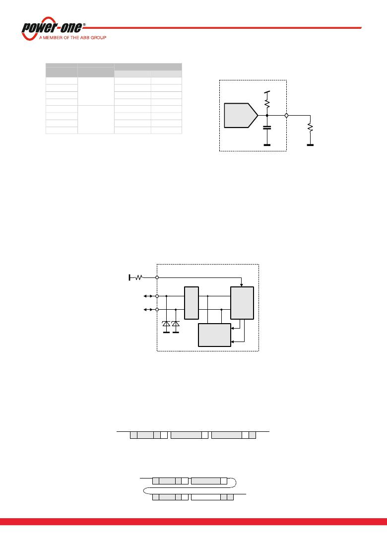
�Figure� 35� -� I� 2� C� address� and� protocol� setting�
�I2C� Address�
�R� APS� (Ω)� 1)�
�Protocol�
�Controller� EEPROM�
�2)�
�820�
�2700�
�5600�
�PMBus?�
�0xB0�
�0xB2�
�0xB4�
�0xA0�
�0xA2�
�0xA4�
�3.3V�
�8200�
�15000�
�27000�
�56000�
�180000�
�PSMI�
�0xB6�
�0xB0�
�0xB2�
�0xB4�
�0xB6�
�0xA6�
�0xA0�
�0xA2�
�0xA4�
�0xA6�
�ADC�
�12k�
�APS�
�R� APS�
�1)�
�2)�
�E12� resistor� values,� use� max� 5%� resistors,� see� also� Figure� 35.�
�The� LSB� of� the� address� byte� is� the� R/W� bit.�
�8.14� CONTROLLER� AND� EEPROM� ACCESS�
�The� controller� and� the� EEPROM� in� the� power� supply� share� the� same� I� 2� C� bus� physical� layer� (see� Figure� 36� ).� An� I2C� driver�
�device� assures� logic� level� shifting� (3.3/5� V)� and� a� glitch-free� clock� stretching.� The� driver� also� pulls� the� SDA/SCL� line� to� nearly�
�0� V� when� driven� low� by� the� DSP� or� the� EEPROM� providing� maximum� flexibility� when� additional� external� bus� repeaters� are�
�needed.� Such� repeaters� usually� encode� the� low� state� with� different� voltage� levels� depending� on� the� transmission� direction.�
�The� DSP� will� automatically� set� the� I� 2� C� address� of� the� EEPROM� with� the� necessary� offset� when� its� own� address� is� changed� /�
�set.� In� order� to� write� to� the� EEPROM,� first� the� write� protection� needs� to� be� disabled� by� sending� the� appropriate� command� to�
�the� DSP.� By� default� the� write� protection� is� on.�
�The� EEPROM� provides� 256� bytes� of� user� memory.� None� of� the� bytes� are� used� for� the� operation� of� the� power� supply.�
�Figure� 36� -� I� 2� C� Bus� to� DSP� and� EEPROM�
�SDA�
�APS�
�Address� &� Protocol� Selection�
�SDA� i�
�SCL�
�SCL� i�
�WP�
�DSP�
�Protection�
�EEPROM�
�Addr�
�8.15� EEPROM� PROTOCOL�
�The� EEPROM� follows� the� industry� communication� protocols� used� for� this� type� of� device.� Even� though� page� write� /� read�
�commands� are� defined,� it� is� recommended� to� use� the� single� byte� write� /� read� commands.�
�WRITE�
�The� write� command� follows� the� SMBus� 1.1� Write� Byte� protocol.� After� the� device� address� with� the� write� bit� cleared� a� first� byte�
�with� the� data� address� to� write� to� is� sent� followed� by� the� data� byte� and� the� STOP� condition.� A� new� START� condition� on� the�
�bus� should� only� occur� after� 5ms� of� the� last� STOP� condition� to� allow� the� EEPROM� to� write� the� data� into� its� memory.�
�S� Address� W� A�
�Data� Address�
�A�
�Data�
�A�
�P�
�READ�
�The� read� command� follows� the� SMBus� 1.1� Read� Byte� protocol.� After� the� device� address� with� the� write� bit� cleared� the� data�
�address� byte� is� sent� followed� by� a� repeated� start,� the� device� address� and� the� read� bit� set.� The� EEPROM� will� respond� with�
�the� data� byte� at� the� specified� location.�
�S� Address� W� A�
�Data� Address�
�A�
�BCD.00040_AG� Sep-11-2013�
�S� Address� R�
�A�
�15�
�Data�
�nA� P�
�www.power-one.com�
�发布紧急采购,3分钟左右您将得到回复。
相关PDF资料
PGB1040805NR
SUPPRESSOR ESD 24VDC 0805 SMD
PGB2010402KRHF
SUPPRESSOR ESD 12VDC 0402 SMD
PHW603616
BOX FIBER 63.5X36.5X18.1" GREY
PI-1902
BOX ABS 1.26" X 1.97" X 3.54"GRY
PI-1905
BOX ABS 1.97" X 2.36" X 4.72"GRY
PI-1908
BOX ABS 2.36" X 3.15" X 5.91"GRY
PI-1911
BOX ABS 3.15" X 3.94" X 7.48"GRY
PJ18168HP42
BOX FIBER 20.0X18.0X8.47" GREY
相关代理商/技术参数
PFE8KR100E
制造商:OHMITE 制造商全称:Ohmite Mfg. Co. 功能描述:Powr-Rib Edgewound Edgewound and Round Wire
PFEC2X2CL
功能描述:FITTING END CAP POLY CLR 2 X 2" RoHS:否 类别:线缆,导线 - 管理 >> 线槽,走线系统 - 附件 系列:- 标准包装:1 系列:PANDUCT® 附件类型:盖 - 线管 适用于相关产品:Panduit 导管 H 型 高度:- 宽:4"(101.6mm) 长度:36.0"(914.4mm) 颜色:黑 其它名称:298-HC4BL36
PFEC4X4CL
功能描述:FITTING END CAP POLY CLR 4 X 4" RoHS:否 类别:线缆,导线 - 管理 >> 线槽,走线系统 - 附件 系列:- 标准包装:1 系列:PANDUCT® 附件类型:盖 - 线管 适用于相关产品:Panduit 导管 H 型 高度:- 宽:4"(101.6mm) 长度:36.0"(914.4mm) 颜色:黑 其它名称:298-HC4BL36
PFEFAN01
制造商:FAIRFORD ELECTRONICS 功能描述:FAN PFE 1
PFEFAN02
制造商:FAIRFORD ELECTRONICS 功能描述:FAN PFE 2
PFEN57-16
制造商:Woodhead Molex 功能描述:
PFE-P
功能描述:线性和开关式电源 COVER FOR PFE RoHS:否 制造商:TDK-Lambda 产品:Switching Supplies 开放式框架/封闭式:Enclosed 输出功率额定值:800 W 输入电压:85 VAC to 265 VAC 输出端数量:1 输出电压(通道 1):20 V 输出电流(通道 1):40 A 商用/医用: 输出电压(通道 2): 输出电流(通道 2): 安装风格:Rack 长度: 宽度: 高度:
P-FEX-440
制造商:PSM International 功能描述: